
 Alison Langley
MERMAID is a 46′ yawl designed by Sparkman & Stephens and built by Paul E. Luke in 1957. She recently received an electrical-system upgrade and a bank of lithium-ion batteries. The new system adds enormous battery capacity and greatly reduces recharging time.
It’s not often that I’m at anchor in a quiet Maine harbor as the morning fog lifts and the cockpit discussion turns to how nice it is that there’s an espresso machine aboard—and, thanks to the new battery bank, we don’t have to fire up the generator to brew a second round. More often, when a boat is on the hard, I discuss with a client how to get more battery capacity and charging ability so that on their next cruise they can bring that espresso machine. That discussion then often turns to the challenges of converting a boat’s current lead-acid batteries to lithium-ion ones, which have greater capacity and more efficiency.
Especially among cruising sailors, this topic comes up often. For more than 50 years, most of us have relied on lead-acid batteries to store what little electricity we could and we’ve been constantly challenged with how to recharge those batteries without extended engine or generator run times.
Lead-acid batteries present several challenges: they are very heavy relative to the energy stored and their electrochemical process is not very efficient either in producing electricity or during the recharge cycle. Typically, lead-acid batteries should not be repetitively discharged below 50 percent of their rated capacity, because doing so diminishes their cycle-life—the number of times the battery can be charged and discharged. When recharging, it can take a considerable amount of time to bring the battery back to 100 percent, because a battery’s internal resistance increases the more the battery is charged. The lead-acid chemistry itself can result in a noticeable decrease in the battery’s efficiency with just a couple of years of use.
Lithium-ion battery technology is lighter and more efficient. For this article, I’m specifically referring to lithium-iron-phosphate (LiFePO4) battery chemistry, or LFP for short, because the LFP battery is the most common lithium-ion battery now being marketed to the marine industry.
What makes LFP batteries so attractive? They are significantly lighter and have a much greater electrical capacity than their lead-acid cousins of the same physical size. LFP batteries have lower internal resistance than lead-acid, so they can be charged more quickly and efficiently. They have considerably greater cycle-life, with potentially thousands of charge and discharge cycles. And they can be deeply discharged, using as much as 90 percent of their capacity without significantly affecting the battery’s life or capacity.
So, what’s the downside? For one, price. While the cost of LFP batteries has come down considerably, they are still two to three times the initial cost of lead-acid batteries. The initial cost, however, can represent an actual savings over several years. As a result of their low internal resistance, LFP batteries can accept a high rate of charge; however, this can put an excessive load on an alternator or battery charger, causing serious overheating. Some lithium-ion batteries have the reputation of being fire hazards, a serious concern aboard a boat. However, the LFP batteries discussed here are significantly more stable than other lithium-ion chemistries, and when installed correctly LFP batteries are very safe. The other challenge is that it’s not simply a matter of swapping out batteries to convert from lead-acid to LFP.
Whether your boat is a good candidate for a LFP conversion can depend on several factors. Do you need or want a significant increase in battery capacity? Is a reduction in battery weight going to be beneficial? Do you have sufficient charging capacity already, or will you need to upgrade your alternator and battery charger? Are you willing to accept the cost of the new batteries, additional components, and the changes to the electrical system that will be required?
 Don Eley
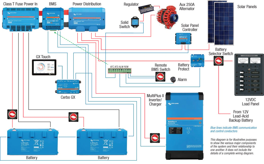
MERMAID’s lithium-ion battery system includes components dedicated to charging, overcurrent protection, and monitoring. For the sake of compatibility and seamless communication, they came from a single manufacturer, Victron Energy.
Any LFP battery installation requires a battery management system (BMS), which can be integral to the battery or an external component. LFP batteries must be automatically monitored and able to shut themselves down if they are being overcharged, are overheating, or are excessively depleted. Because of their ability to produce a huge amount of current instantaneously, there must be appropriate over-current protection (OCP), typically a fuse, as well as wire-gauge (size) considerations. Charging systems—both alternators and battery chargers—must be addressed, since directly charging LFP batteries can lead to fire hazards associated with these other components.
Two categories of LFP batteries are available for marine use. One incorporates its own internal BMS and is often designated as a “drop-in” battery. All the monitoring and control happens within each individual battery. The other LFP category requires an external BMS that not only monitors and controls the battery but also controls the various charging and load components of the system.
While the “drop-in” type LFP battery is generally considered safe in the marine environment, I caution against just replacing one of your lead-acid batteries with an LFP without seriously considering its impact on the rest of electrical system. Another challenge is that the internal BMS can shut down the battery with little or no warning if it’s being overcharged, it’s overheating, or nearing its limit of discharge. Most of us have observed this phenomenon with a battery-operated hand tool that simply shuts off because the battery has reached this discharge limit. Now imagine being in the fog, in a narrow channel with other traffic around, and suddenly all of your electronics shut down.
While an external BMS makes for a more complex installation, it allows for the close monitoring of the battery’s temperature, cell voltage, and state of charge, and the BMS can activate an alarm warning of an imminent battery shutdown. The external BMS also serves as a hub to communicate with all the other system components. Based on information from the battery, the BMS can control the alternator output, the battery charger, solar panels, and power supplied to loads.
Safety is paramount regardless of which category of LFP battery is installed. The American Boat and Yacht Council (ABYC), which sets industry standards for all the various systems on recreational boats, has developed a specific standard (E-13) that addresses the installation of LFP batteries. In combination with two other standards—E-10 for storage batteries and E-11 for AC and DC electrical systems—this lays out the requirements that are critical to a safe installation. In this article I will refer to these ABYC standards; however, anyone installing an LFP battery system must be familiar with the ABYC standards as well as the specific battery manufacturer’s recommendations.
 Don Eley
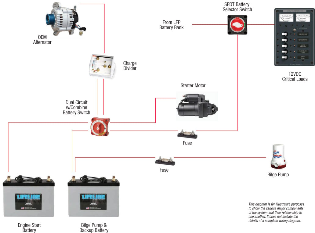
MERMAID’s electrical makeover includes a backup lead-acid battery bank to which the bilge pump can be directly wired. Critical DC loads, such as navigation devices, can be maintained if the lithium-ion battery system shuts down.
To address these safety issues and the details of converting a vessel from a lead-acid to an LFP battery system, I’ll use one of my recent electrical-design projects as a case study. MERMAID, a 46′ Sparkman & Stephens–designed ketch, was built by Paul Luke in East Boothbay, Maine, in 1957. Originally designed for long-range sailing, she has also proven herself all over New England as a top performer in classic-yacht racing. For more than 40 years, she has been meticulously maintained for three different owners by Seal Cove Boatyard in Brooksville, Maine—the yard that accomplished the new system’s installation.
A new owner plans to carry on MERMAID’s long tradition of cruising and racing but also wants to update numerous systems, including replacing the auxiliary diesel, adding refrigeration, and upgrading to LFP batteries with solar panels and shore power connections. The original electrical system incorporated just two lead-acid batteries using the traditional “one-two-both” battery switch. It was time for a renovation.
The start of any electrical project begins with understanding the needs, wants, and expectations of the owner. Typically, this begins with questions about how the boat will be used, what the electrical loads will be, what the owner’s expectations are for both use and charging intervals, and how costs and budget play into these decisions. With a large or complex system, I will often develop a load analysis using a spreadsheet incorporating all the boat’s loads and look at such use scenarios as at-anchor, under way sailing, and under way using power. From this analysis, battery capacity and charging needs can be developed. Then I can put together a list of components, arrange their layout and location, determine wire runs, wire gauge, and the appropriate overcurrent protection.
With MERMAID, there were very clear goals and expectations: coastal New England cruising, classic yacht racing, extended times at anchor with minimal engine run time, and occasionally being dockside with shore power. In this refit, with most of the existing electrical systems being either upgraded or replaced, it allowed for a “clean sheet approach” to the design.
 Don Eley
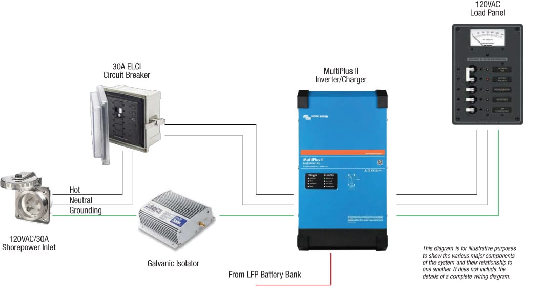
The boat’s AC electrical system can be supplied by shore power, or by the batteries through an inverter. The galvanic isolator is designed to allow a 120VAC fault current a path back to earth without passing through the water—a danger to swimmers—and at the same time prevent low-voltage DC current, which can cause galvanic corrosion, from passing between boats connected to shore power.
Knowing that MERMAID’s LFP battery system was going to be fairly sophisticated, with several interdependent components, including the batteries, battery charger, alternator, inverter, and solar panels, using an external BMS was most appropriate. I have found that a practical approach to a design such as this is to try to use a single manufacturer for the various components; this ensures the components can communicate with one another for monitoring and control, and help with resolving an issue within the system involves a single source, with no finger-pointing about whose component is to blame. There are several reputable suppliers for marine LFP systems. For this project, we chose to use Victron Energy.
Batteries, Battery Switches, and Overcurrent Protection
With the estimated loads on the battery bank, and taking into consideration acceptable charging times, we determined that two 12V, 300Ah LFP batteries configured in parallel would meet expectations. Totaling 600Ah (7.68 kWh) and with the ability to discharge down to 10 percent of capacity (90 percent depth of discharge or “DoD”), this nets 540Ah (6.14 kWh) of usable power. Each battery weighs 64 lbs, for 128 lbs total; they have a combined footprint of about 18″×18″. By comparison, a lead-acid battery bank with approximately the same net amp-hour capacity would have required four 4D batteries weighing 120 lbs apiece, for 480 lbs total and a combined footprint of 20″×42″. From a weight and size perspective, the LFP batteries have a clear advantage.
 Don Eley
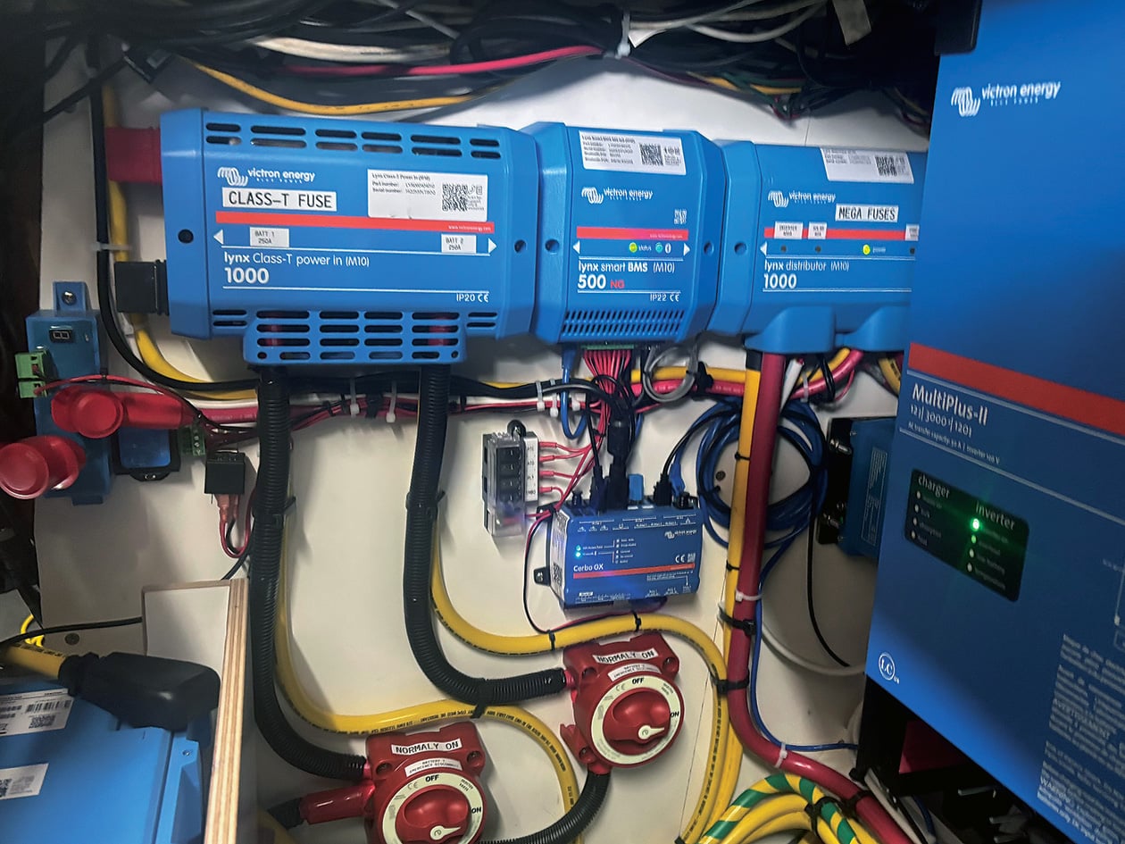
The system’s components are carefully laid out in the boat’s starboard cockpit locker, where they are accessible but out of sight.
The batteries are mounted in a cockpit locker in enclosures that ensure adequate ventilation to dissipate heat, keep the batteries secured to prevent movement, and protect them from exposure to water that may get into the space. Each battery has its own single-pole, single-throw (SPST) switch located just outside the battery box and within easy reach of the cockpit. This allows for each battery to be independently separated from the system if necessary.
A significant issue with LFP batteries is their ability to discharge extremely high amounts of current in a short period of time. If a short-circuit occurs, these particular 300Ah batteries can produce upwards of 15,000 amps apiece, making overcurrent protection not only paramount, but also mandatory.
A fuse or circuit breaker has three distinct ratings, all of which are critically important. First is the nominal amperage rating, which is the number typically associated with a fuse’s “size”: 10-amp, 20-amp, etc. This is the maximum amount of current that can safely pass through the fuse without it “blowing,” or opening the circuit. Designed to protect the wiring from being exposed to excessive current, it needs to be located as close as practical to the power source. Next is the voltage rating. This is the maximum system voltage the fuse is designed to operate in. With 12V systems, this isn’t typically an issue since most low-voltage marine fuses are rated at 32V. However, it can become a problem with DC systems at 48V, where finding fuses with a sufficient voltage rating can be difficult.
The last rating, and arguably the most important, in this scenario, is the ampere interrupt capacity (AIC). This is the maximum short-circuit current the fuse can handle without being damaged, such as welding it in the closed position, thus making it no longer able to interrupt the current flow. The AIC rating is especially critical when selecting fuses for the potentially high short-circuit amperage of LFP battery systems. The Class-T fuse, with an AIC rating of 20,000 amps, is the industry standard for initial overcurrent protection in LFP systems.
On MERMAID we used two 250-amp Class-T (meant for high-amperage DC applications) fuses incorporated in the power-in module, one for the output of each battery. These have a nominal rating of 250 amps, a maximum voltage rating of 125V DC and an AIC rating of 20,000 amps. ABYC requires the initial fuse with appropriate ratings be within 7″ of the positive battery terminal or within 40″ if the conductor is contained within a conduit or protective sheath. We used “split-loom” tubing over the positive conductor along the route to meet this requirement.
A note on the wiring used for this project: All the conductors are rated as “Type 3, Marine Grade, BC5W2.” This designation indicates that the conductor is multi-strand tinned copper designed for the marine environment with insulation rated for 600V at 105°C (221°F) in dry situations and 60°C (140°F) in wet conditions. This is the marine-industry standard and these specifications are clearly indicated on the insulation jacket of the conductor.
There is some debate over whether the battery switch or main fuse should come first. If the fuse is first in line, it will protect the conductor downstream, which is rational. However, this makes servicing the fuse hazardous since it’s always connected directly to the LFP battery. My choice is to put the battery switch first, immediately after the battery, and then the Class-T fuse. This allows you to completely isolate the battery from the rest of the system and de-energize the fuse for service.
The progression of components in this installation is: LFP battery, the battery switch, followed by the Class-T fuse and main bus bar in the power-in module; all within the 40″ ABYC standard.
The Battery Management System
 Truman Forbes
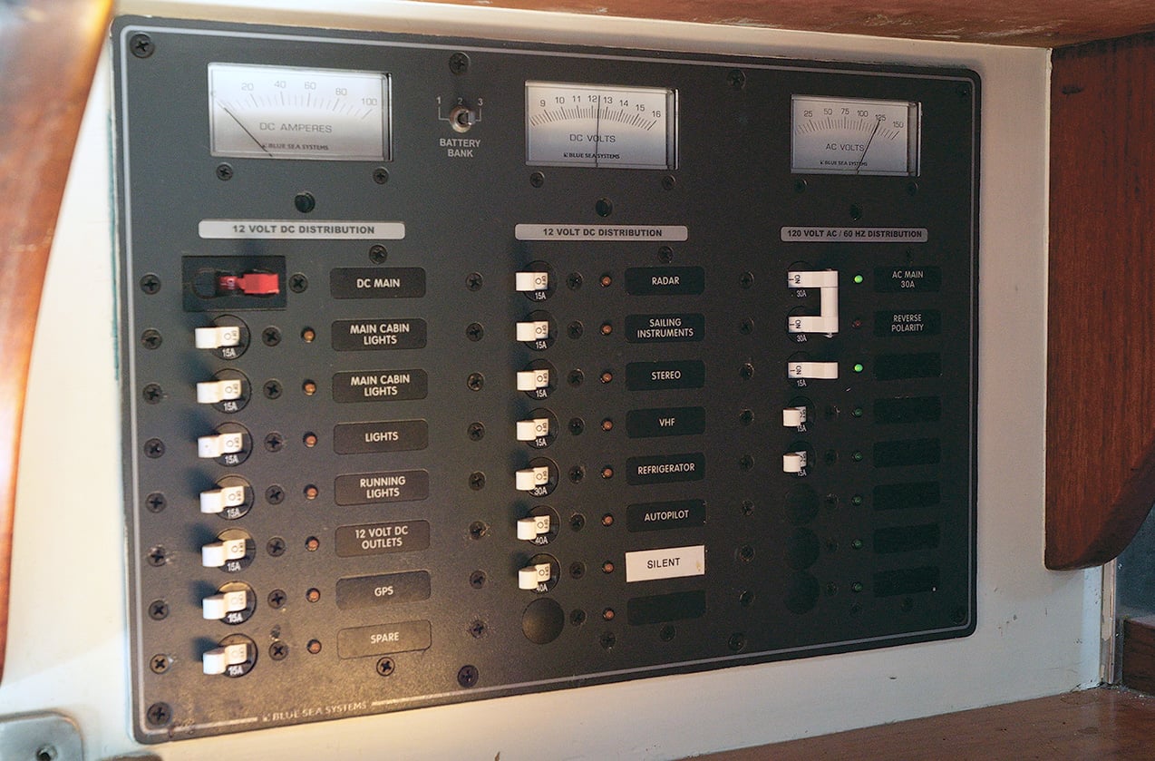
The boat’s DC and AC loads are managed by a standard electrical panel. Adjacent to this, and not show here, is a small touch screen for monitoring the lithium-ion battery system.
The Victron Lynx BMS used in MERMAID is an external module that continuously monitors the LFP batteries and communicates with several other components to control the charging and discharging. With a 500-amp normally open (N/O) contactor relay, it can automatically open the circuit and disconnect the batteries from the rest of the system when warranted.
The BMS serves as a main hub directly connected to the power-in module on one side, with its Class-T fuses, and the distribution module on the other side, with overcurrent protection to each of the system’s loads and charging sources. Combined, the three modules create the central nervous system with command and control and overcurrent protection in one place.
The battery communication with the BMS is via a daisy-chained three-pin cable. Though only two LFP batteries make up the battery bank on MERMAID, the BMS can handle up to 20-batteries.
There are four control functions incorporated into the BMS. One is programmed to set off an alarm when the BMS senses the system is nearing its shut-down point, allowing time to either reduce loads or to start charging the batteries. A second function allows for the use of a remote control of the system shutdown. For this, I’ll typically use a standard SPST on-off battery switch, even though it doesn’t carry much current, and designate it as “emergency off.” It must be located in a readily accessible position so that, if the need were ever to arise, anyone aboard could quickly shut the batteries off by remotely opening the BMS contactor. The other two control functions from the BMS are the Allow to Charge (ATC) and Allow to Discharge (ATD) signals.
 Don Eley
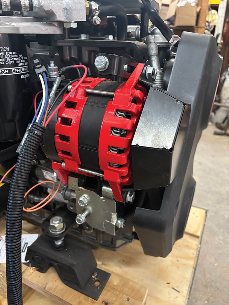
A 250-amp alternator was added to the engine to charge the lithium-ion batteries. The engine’s standard 120-amp alternator remains, to charge the lead acid batteries. The two systems are independent of each other.
MERMAID’s new auxiliary diesel is set up with two independent alternators. A 250-amp alternator exclusively charges the LFP battery bank. A second, smaller alternator charges the engine start and emergency backup batteries (which are part of a later discussion). The ATC signal from the BMS effectively turns the 250-amp alternator on or off by powering the alternator’s regulator. The ATC signal will also turn the alternator off before a system shutdown protecting it from an open circuit scenario that can seriously damage the alternator. Independently, the alternator’s regulator senses the alternator temperature, reducing its output, when necessary, to keep the alternator from overheating.
The ATD signal controls power to the 12V DC load panel via the battery-protect relay. Under normal operating conditions, the relay allows power to be supplied to the panel. If, however, the BMS senses a low battery condition, or any situation outside of its normal operational parameters, the alarm will sound before eventually disconnecting power to the load panel.
Communication Hub and User Interface
In addition to the BMS there is the Cerbo GX—a dashboard that displays the data managed by the BMS. It serves as a communication center and acts as an integrated hub that connects, monitors, and controls other system components such as the inverter, the battery charger, and the solar charge controller. One of its functions is to implement the “allow to charge” and “allow to discharge” signals for these devices.
The Cerbo GX gathers real-time data on the batteries’ state of charge, temperature, voltage, and current flow that is then displayed on the GX Touch, a user-interface screen. System monitoring and control is thus readily accessible and straightforward. The system information can also be pulled up with the Victron app on a smart phone or, when interfaced with NMEA 2000 (the universal marine electronics standard that connects various electronic devices), using a multi-function display (MFD). The Cerbo GX also stores historical data so that past power usage, charging information, and trends can be retrieved.
On MERMAID, we installed a combined 3kW inverter and 120-amp battery charger, the MultiPlus II. Advanced control of the inverter-charger is accessed using the GX Touch-Cerbo GX providing remote on-off control and the ability to set current limits for the shore-power input, thus avoiding tripping the dockside circuit breaker.
While all of this may seem overly complex, once the system was installed and operational, most of the functions were happening in the background, with the GX Touch as the only part of the system the user needed to interact with.
Engine Start and Emergency Backup Battery System
When assessing the risk of any boat system, I’ll look at the probability of a particular failure and weigh that against the consequence of the failure. The system can then be designed to reduce the risk of failure and mitigate the consequences. In MERMAID’s electrical system, while the probability of an LFP battery shutdown would be relatively small, the consequence of a sudden loss of power can be significant. Electrical loads powered by LFP batteries, and relevant to safe navigation and operation, present particular challenges.
ABYC recognizes this risk and in its E-13 standard recommends an alternative power source, separate from the main LFP battery system, for engine starting and for the backup of critical navigation components. With MERMAID’s design, we incorporated two Group-31 AGM lead-acid batteries. One is specifically for engine starting, with a high cold-cranking amp (CCA) capacity; the other is a deep-cycle, high amp-hour battery as backup power for critical loads. In the unlikely event of an LFP system shutdown, this second battery can be manually switched to power the VHF radio, radar, chartplotter, and navigation lights. The single-pole, double-throw (SPDT) battery switch allows for the selection of one of the two battery sources. It does not, however, parallel the two battery systems. It’s either one battery or the other—not both.
A unique challenge emerges when powering an electric bilge pump with LFP batteries. In a typical marine system, the bilge pump is wired directly to the battery so that it remains operable even if the battery switch is in the “off” position. A fuse, close to the battery is incorporated in the circuit for overcurrent protection. However, under no circumstances can a load or charging source be wired directly to an LFP battery with an external BMS. This will effectively bypass the BMS leaving no control over the battery and creating a potentially dangerous situation, such as an uncontrolled thermal runaway. If the bilge pump comes after the BMS, and the BMS were to shut down, the bilge pump would then lose power. In order to address this potential loss of LFP battery power, MERMAID’s bilge pump is instead wired directly to the lead-acid battery that also serves as the critical-load backup. A fuse is provided at the battery, and power to the bilge pump remains intact regardless of the LFP battery status. This assumes, of course, that the lead-acid battery has sufficient charge. When an LFP battery with an internal BMS is used then it is acceptable to wire the bilge pump directly to the battery, with appropriate overcurrent protection.
Because the charging characteristics of lead-acid and LFP batteries are so very different, it’s imperative that the two battery systems remain separate. MERMAID’s two lead-acid batteries are charged by the engine’s OEM 120A alternator through a Pro Mariner charge divider. The aforementioned 250-amp auxiliary alternator only charges the LFP batteries. With the engine running, both sets of batteries are charged independently, with no crossover between the two systems.
Shore Power
MERMAID will spend some of her time dockside plugged in to shore power. A 30A, 120VAC system was installed to comply with the most recent ABYC E-11 standard for AC and DC electrical systems. The 120VAC shore power comes aboard at the three-wire twist locking socket. The hot and neutral wires are run to a 30A two-pole circuit breaker called an ELCI (equipment leakage circuit interrupter), while the grounding wire continues uninterrupted to the galvanic isolator.
The 30A ELCI circuit breaker serves two purposes: As with any overcurrent protection device (OCPD) it is designed to protect the boat’s wiring in the event of a short circuit or current overload. If the boat draws more than 30 amps the circuit breaker will trip. The ELCI portion is continuously monitoring the balance of current between the hot and neutral conductors. If an imbalance of 30mA or more is detected it will instantly trip the circuit breaker (30mA = .030A). This acts similarly to the household GFCI outlets we are all familiar with that serve kitchens, bathrooms, or patios. However, it trips at a higher mA limit and is designed to detect electrical current leaking into the water surrounding the boat, thus protecting swimmers in the area from a potentially fatal shock hazard. An ELCI device is required on any new or updated shore-power system.
The galvanic isolator is in series with the grounding conductor. It’s designed to allow a 120VAC fault current aboard the vessel a path back to earth without passing through the water and at the same time prevent low-voltage DC current, responsible for galvanic corrosion, from passing between vessels connected to shore power.
When the boat is plugged into shore power, all the current is directed to the MultiPlus II Inverter/Charger. It then passes current through to the 120VAC load panel and at the same time powers up the battery charger for the LFP batteries. Since the batteries can accept a charge at a high rate, it’s important to limit the total input current in order to avoid tripping the dockside circuit breaker. Maximum input current can be set via the GX Touch. Normally this will be 30A; however, if less current is available at the dock a lower limit is easily adjusted.
Another function of the MultiPlus II is to supplement the 120VAC loads. For example, if the 120VAC loads exceed the preset shore-power current limit, the inverter will then take power from the LFP batteries to help supply those loads and avoid tripping the dockside circuit breaker. Once the 120VAC loads are reduced it will then continue with its battery-charging function.
The MultiPlus II is also a stand-alone inverter, converting 12VDC battery power to 120VAC when the vessel is not dockside. With a 3,000W capacity, the inverter has no issues running the most common appliances in the galley, such as an espresso machine or induction cooktop.
Performance Testing
 Alison Langley
MERMAID’s ambitious cruising and racing agenda will be well served by the great capacity and quick charging of lithium-ion batteries.
The final step in system design is performance testing. With all the components installed, their firmware updated, and operating parameters set, it’s time to run the system to ensure that it is performing as designed. On MERMAID’s initial startup, the two 300Ah batteries were recognized and each individual cell voltage was displayed. Connected to shore power, the battery charger quickly brought the batteries to full charge, resetting the state of charge to 100 percent. With the shore power disconnected, numerous 12VDC and 120VAC loads were brought online. After several hours, the battery bank was drawn down to 10 percent of its capacity and the alarm sounded, indicating a shutdown was coming soon. Shore power was reinitiated and the batteries came back to fully charged within three hours.
With the engine running, alternator testing provided similar results. Discharged batteries recovered quickly, with system monitoring via the GX Touch being fairly intuitive.
 Truman Forbes
Author Don Eley tends to final details aboard MERMAID during her 2026 commissioning.
Though the possibility of a system failure is never eliminated entirely, I feel that sufficient redundancy has been built into MERMAID’s battery system to mitigate these risks and allow the boat to be operated safely. The recent work on MERMAID illuminates the details necessary for a successful LFP battery conversion, and I hope it encourages owners of similar yachts to not shy away from adopting new technology in a classic vessel. 
Don Eley is professor emeritus at Maine Maritime Academy. Now retired from teaching, he continues to design and consult on marine electrical systems with his firm Yacht Engineering Systems. He is an ABYC-certified advisor. Recent projects range from the 156′ schooner ERNESTINA-MORRISSEY to electric propulsion for Herreshoff 12½s.